Component Manufacturing for More than a Century
Hundreds of Products. Thousands of Applications. One Goal: Your Success


Our Commitment to Our Customers
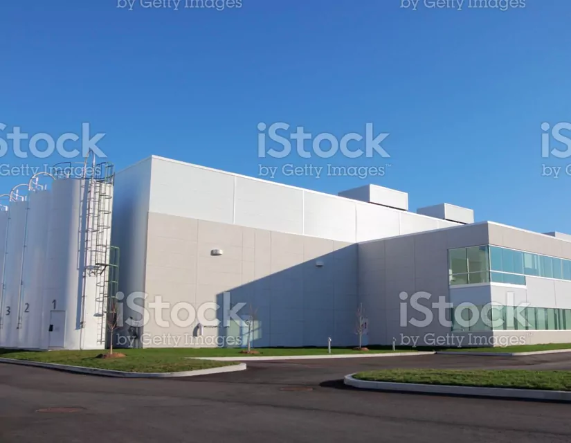
Kelco Industries is a market leader in cost-effective, high performance, custom engineered components for a wide variety of industries. We invest in the latest technologies and top talent, and because we are privately held, we answer only to our customers – so we can make fast decisions that move our business and our customers forward.
Kelco History
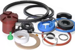
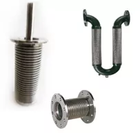
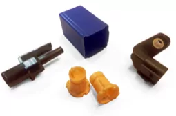
Kelco Industries is a market leader in cost-effective, high-performance precision engineered components used across a broad range of industries. All Kelco industrial components are clean, sanitary, and made in America.
Four companies – Guardian Electric, Advanced Molding Technologies, Flex-Weld and Western Consolidated Technologies – come together under the Kelco Industries banner with over one hundred years of expertise crafting industrial product lines and innovative custom engineered solutions for our customer’s unique challenges. Each division brings its rich history of excellence – from responsive turnaround to dependable customer service – to exceed your expectations:
Media & Events
-
 News
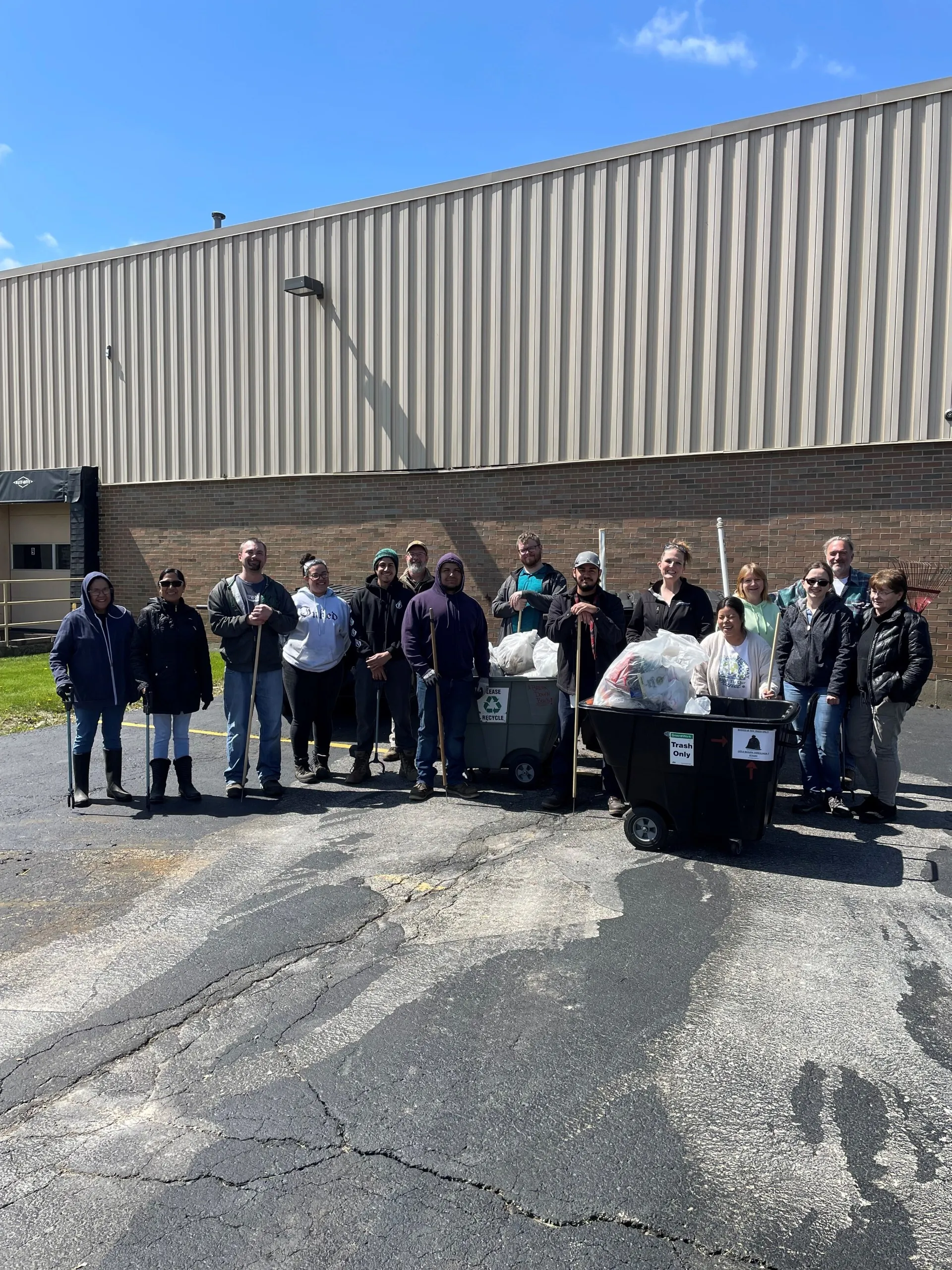
NewsCleaner and Greener: How Kelco is Celebrating Earth Day 2024
Read more: Cleaner and Greener: How Kelco is Celebrating Earth Day 2024
-
News
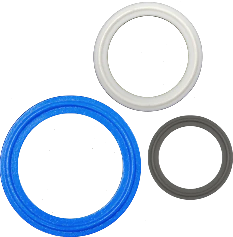
New Kelco Sanitary Gaskets
Read more: New Kelco Sanitary Gaskets
-
News

KELCO: Supporting Those in Need at the Holidays
Read more: KELCO: Supporting Those in Need at the Holidays

